Negative Trigger Relay Wiring

nest Hello Wiring Diagram, Nest Hello Advanced Wiring Diagram, 6.25 MB, 04:33, 63,749, gt8monster, 2018-06-16T10:14:46.000000Z, 19, Nest Hello Doorbell: 18 Questions/Answers You Need To Know - Smart Home Point, www.smarthomepoint.com, 1057 x 852, png, nest diagram hello doorbell wiring google camera chimes chime install multiple lh4 googleusercontent answers questions know need pre, 20, %ef%bb%bfnest-hello-wiring-diagram, Anime Arts
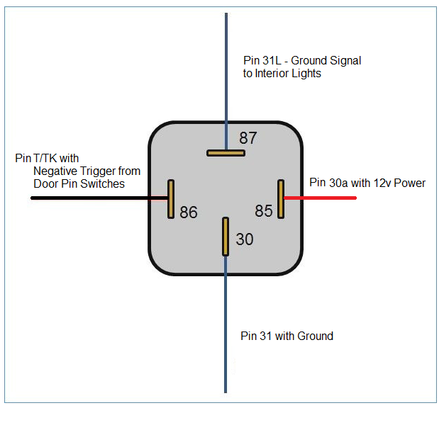
The other leg for the relay coil goes to the negitive trigger from the haltech. September 22, 2013 assuming that the haltech only grounds out that circuit when it's powered up and running, you could just run a single, large fused wire from battery straight to the 30 terminal on the relay, then loop a small wire over to 85. The load (lights, fan, etc. ) is connected through pin 87 to the negative terminal of the power source. Once this has been done, connected pin 86 to the positive terminal of the source as well.
Yes a diode will stop the 12 volts from getting to the device. However, i think that the backlash from the relay is what is taking your device out. Negative switched signal pin 30: Wire this directly to the positive power source. Wire this pin directly to the positive power source. Wire this pin directly to the ground switched on/off signal. This pin will be connected to your new device. This device will power on when the relay gets the signal via pin 86. 2. 3 how to wire a 5 pin relay with a negative trigger?
NEGATIVE TRIGGER RELAY WIRING DIAGRAM - YouTube

KS 4574] Negative Trigger Fog Light Relay Wiring Diagram in 2021 | Light switch wiring, Fog
![Negative Trigger Relay Wiring KS 4574] Negative Trigger Fog Light Relay Wiring Diagram in 2021 | Light switch wiring, Fog](https://i.pinimg.com/originals/8f/64/ce/8f64ceecc2b3e46d5133652b7ea8dcb3.jpg)
Using A Tim05/Tim06 To Supply A Negative Output Signal | REDARC Electronics

Relay Wiring Diagram Negative Trigger

Powering A Relay With A Negative/Ground Feed | Relay, Car audio installation, Car mechanic

Relay Wiring Diagram Ground Trigger - Doctor Heck

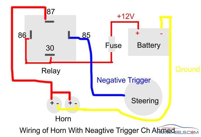
How to install Relay with Horn? - Mechanical/Electrical - PakWheels Forums

Hournine Racecraft - Bosch Relay Being Triggered Automatically
Diode Isolate Negative Door Trigger - Relays/Switches/Diode Wiring Diagrams - Lockdown Security

Relay Wiring Diagram Negative Trigger - KIMRAESHIELDS
